-
Notifications
You must be signed in to change notification settings - Fork 56
ConstructionGuide
Let's go through a step by step soldering and assembly of the Goodwatch30 board.
Hot air rework station is probably necessary for balun only. All other components can be easily soldered with a fine tipped soldering iron, thin solder wire or solder paste and lots of flux. That being said, I find it easier to do the whole thing with hot air station and then do touch up with a soldering iron. Also, I don't have a solder paste stencil, so I'll be applying it by hand.
To start off, lets do the MCU first. This is entirely too much solder paste, but it can easily be cleaned up later.
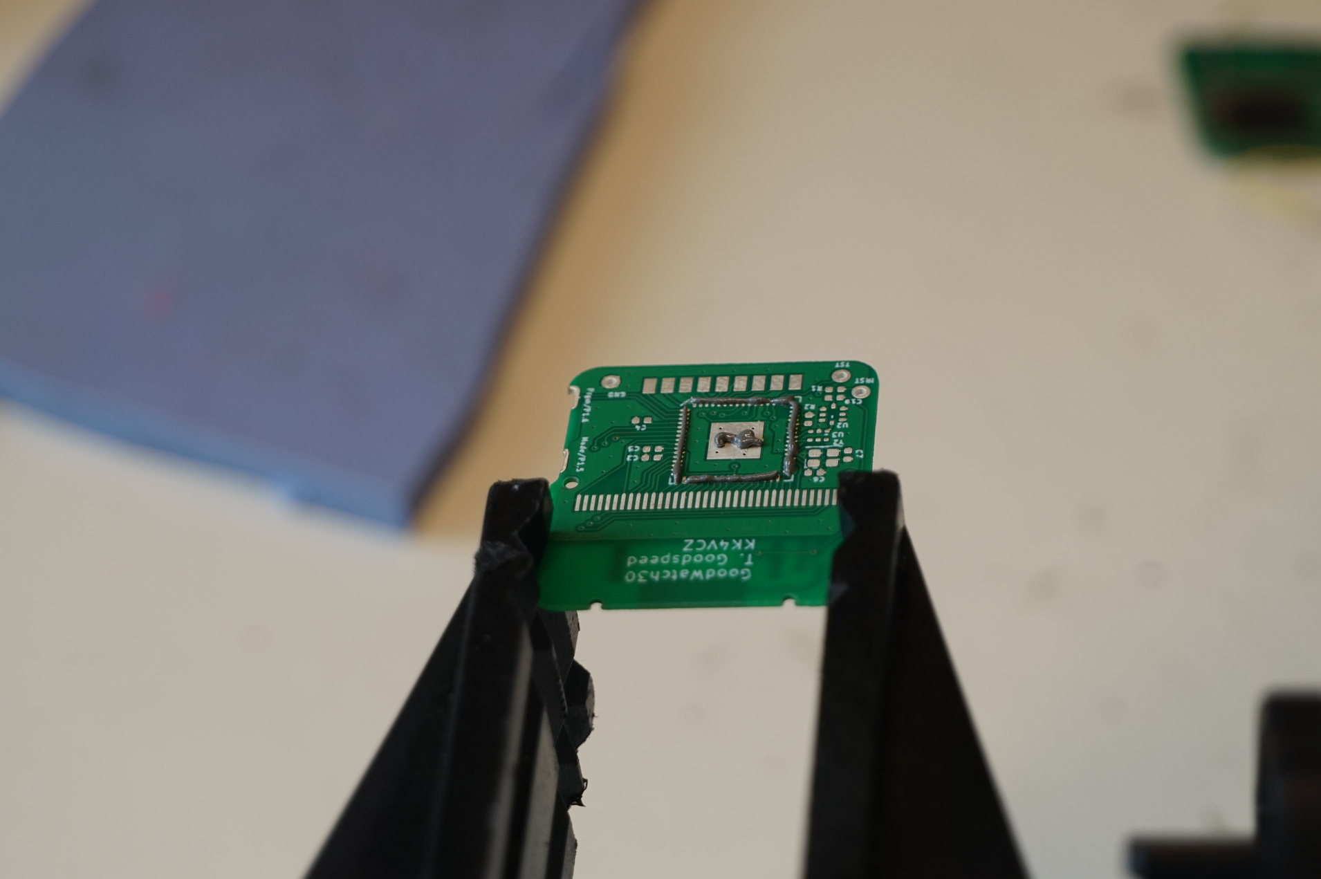
Orient the MCU correctly and place it on top. It doesn't have to be perfectly aligned as surface tension of melted solder will pull it in place.
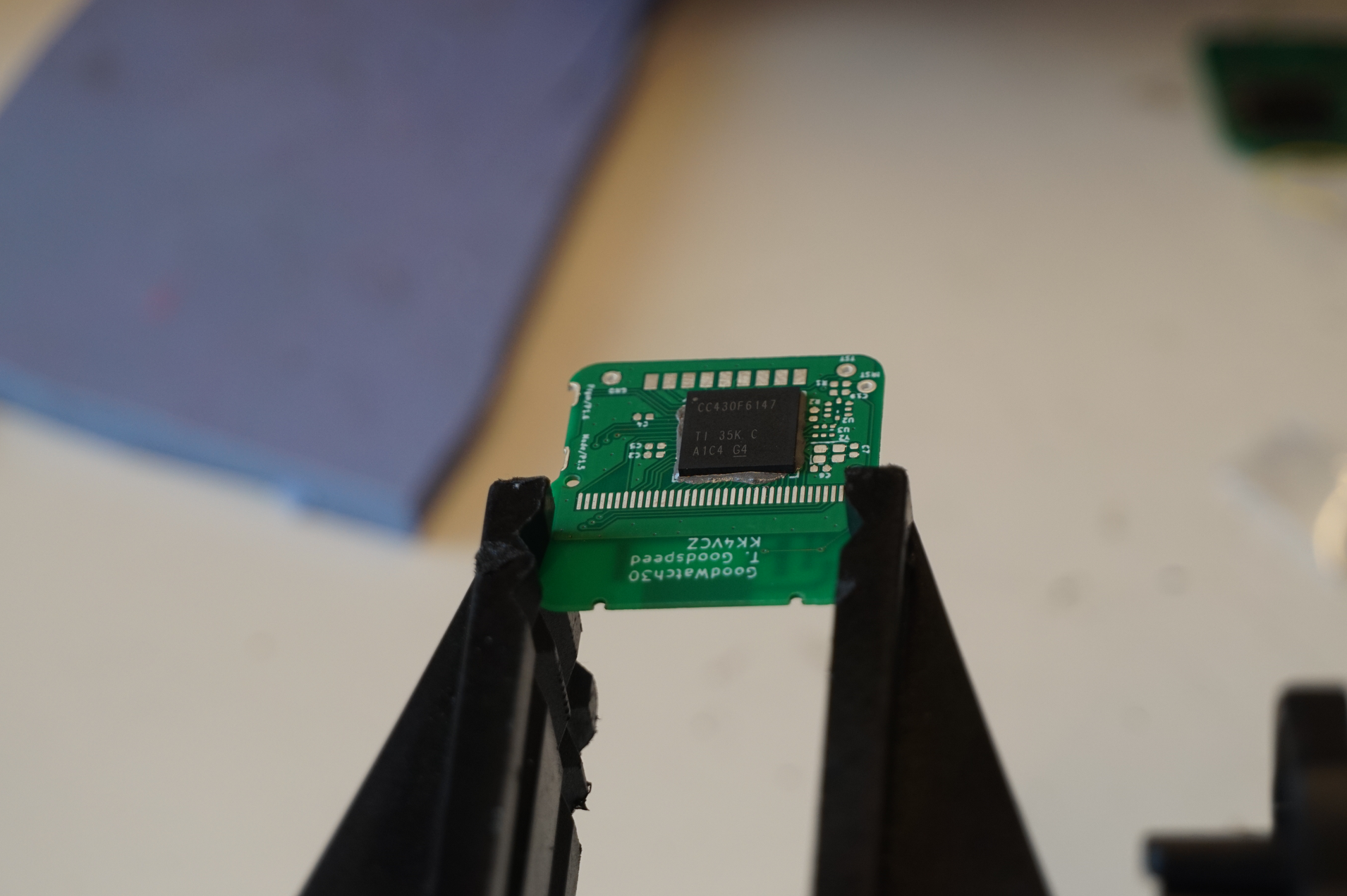
When all the solder reflows, if the MCU isn't properly aligned, you can touch it with tweezers to put it in the correct place.
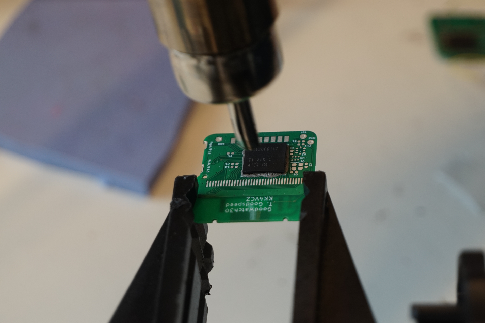
Too much solder paste will likely bridge pins.
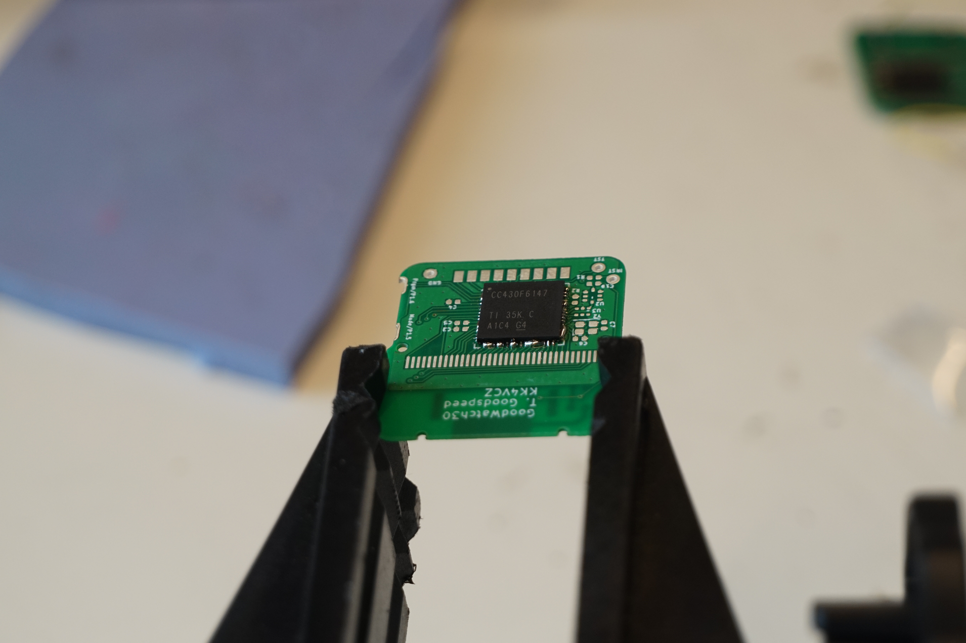
This also easily happens with hand soldering but is easily fixed with solder wick.
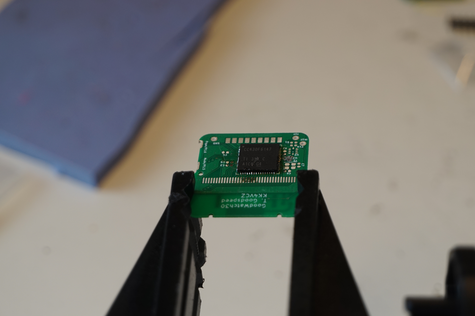
This is the reason we do the MCU first. It's much easier to fix these bridges when other components aren't in the way.
Now, repeat the same process with the radio subsystem. Hardware Bill Of Materials for Goodwatch30 has three options for filter U2. Choose one that is appropriate for your use case and pay attention to component orientation.
U2      0500LP15A500            712-1117-1-ND       0805     1     500MHz Low Pass Filter (70cm usage)
U2      0868LP15A020E           712-1585-1-ND       0805     1     868MHz Low Pass Filter (EU unlicensed usage)
U2      0915LP15B02             712-1122-1-ND       0805     1     915MHz Low Pass Filter (33cm usage)
If you are doing these by hand, I suggest doing the bigger components first.
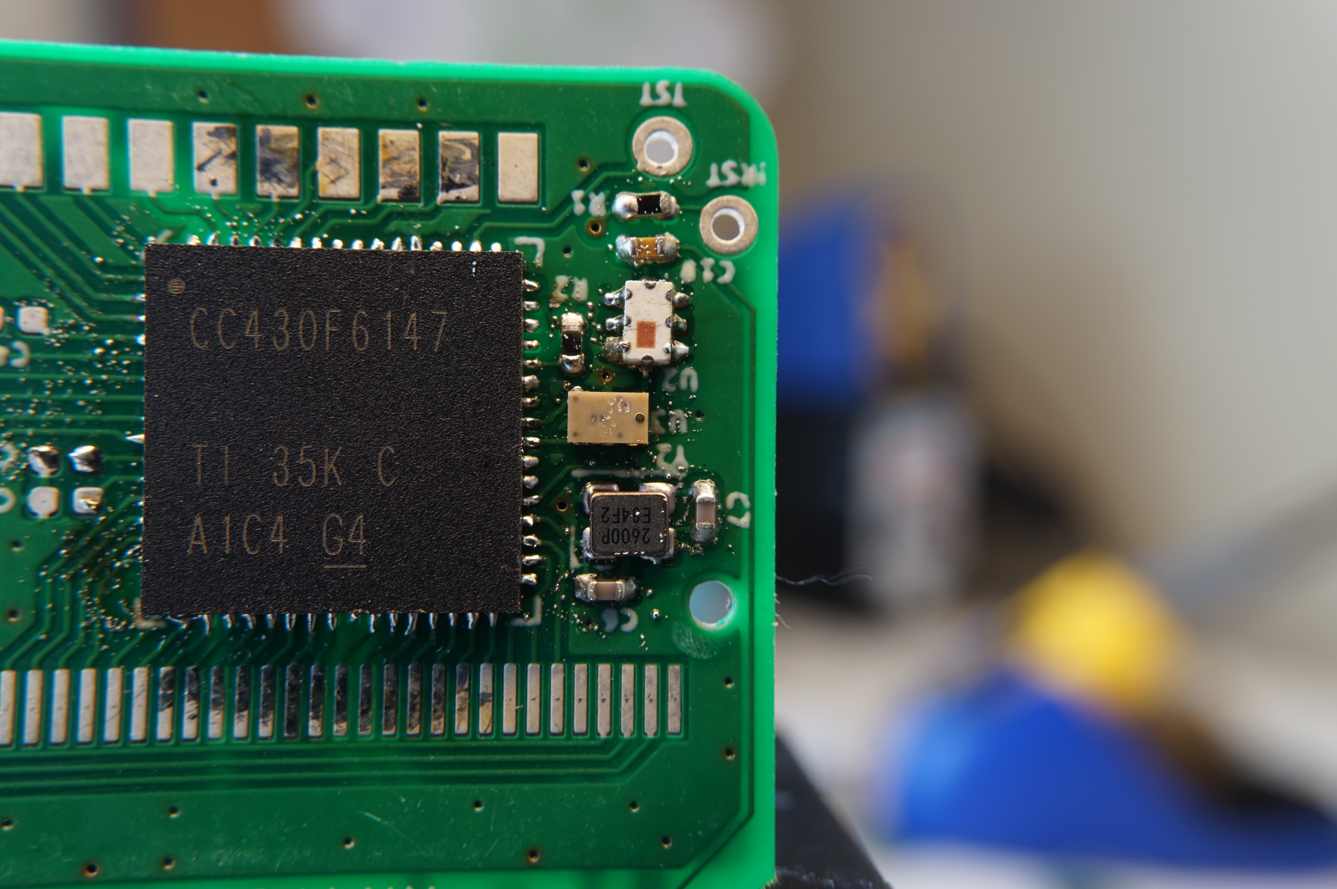
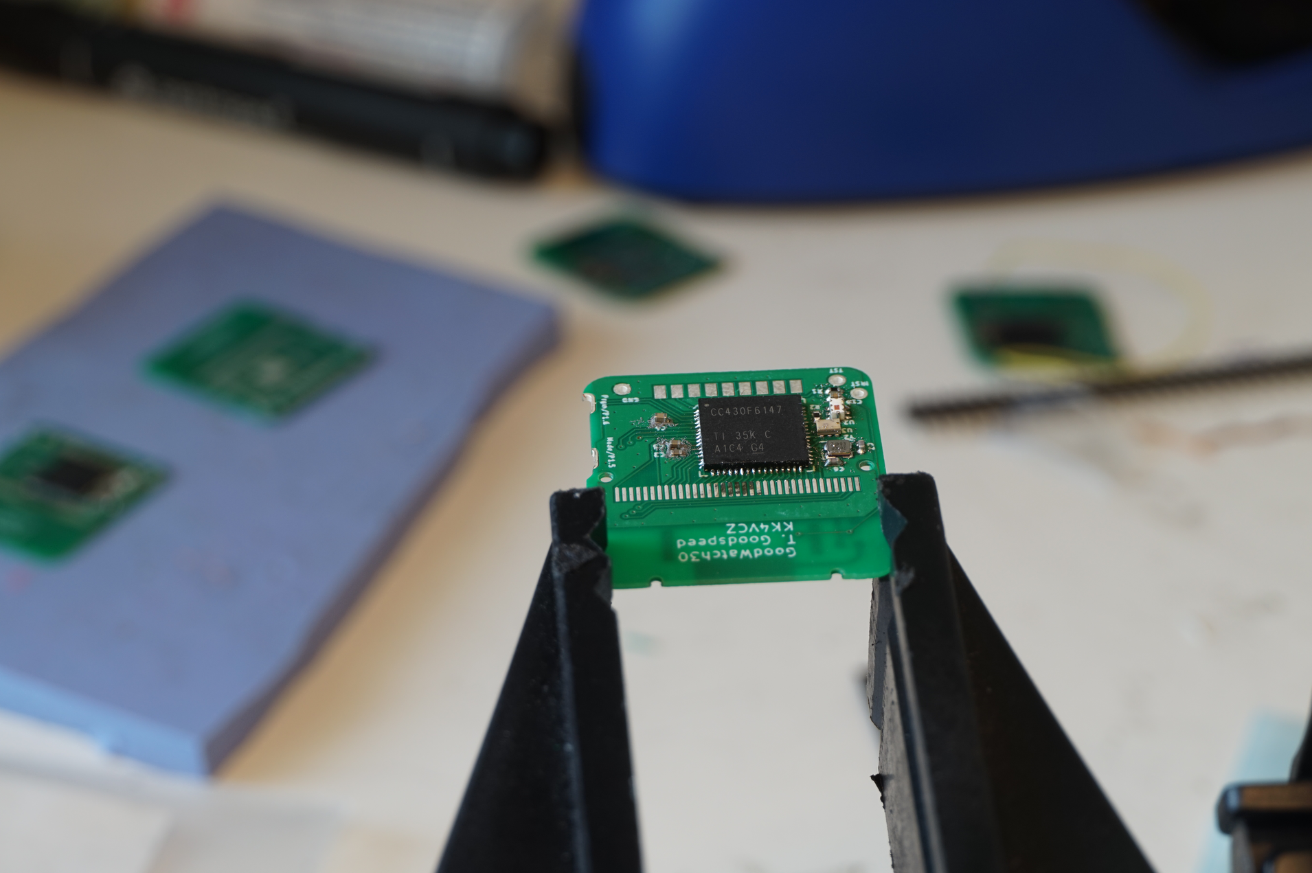
Pay no attention to leftover dots of solder and flux residue, we'll clean that up with alcohol after the whole board is done.
Hard part is done, just a few components on the left and then the other side of the board.
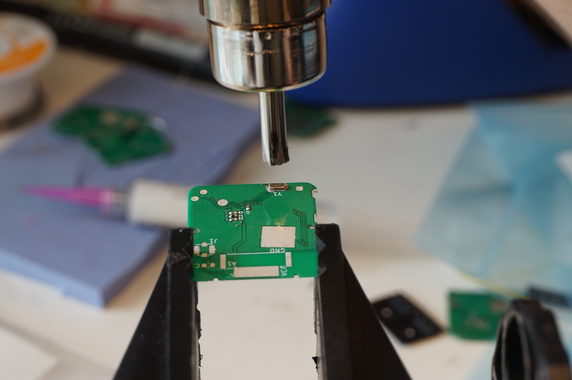
Bottom part of the board has only four required components, all easily done either by hand or with hot air.
And that's it. Give the whole board a wash in isopropyl alcohol, inspect it for solder bridges and we are done!
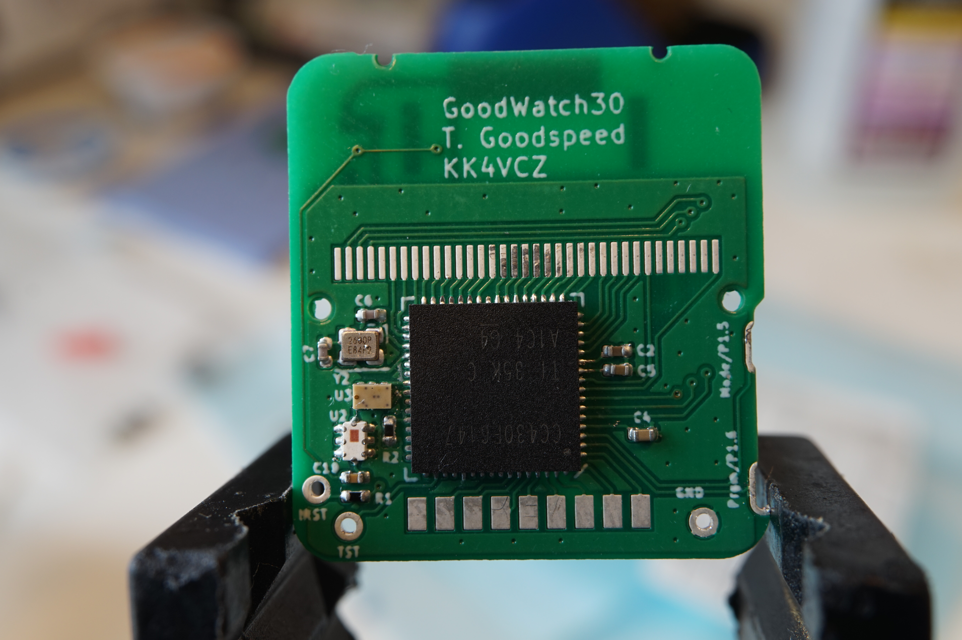
Now, consult the BootStrapLoader or EnergyTrace page for details on how to build and flash the firmware. After that, we can continue on assembling the watch case.
Onto gutting the watch case. Undoing the 4 screws reveals the inner case.
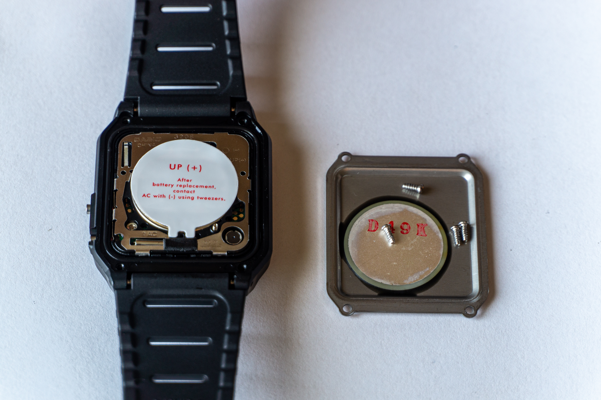
We don't want to short anything, so first unlatch the battery using fine tipped tweezers or a needle.
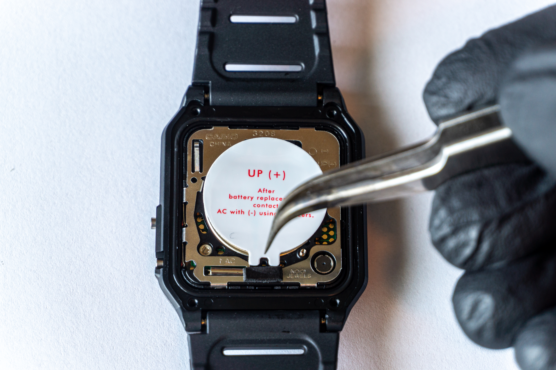
Pay close attention to that buzzer spring, it easily falls out.
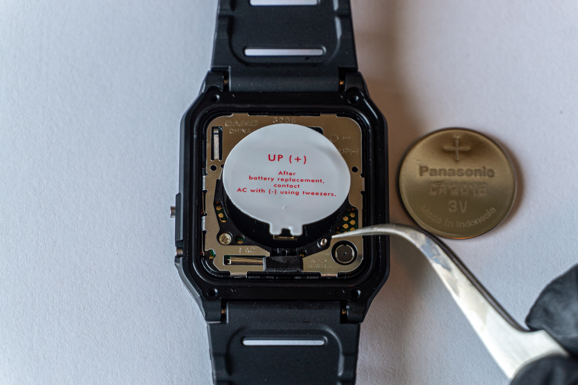
The inner case is held in place via two plastic detents on top and the bottom side. Depress the one on top and you can pop the case out.
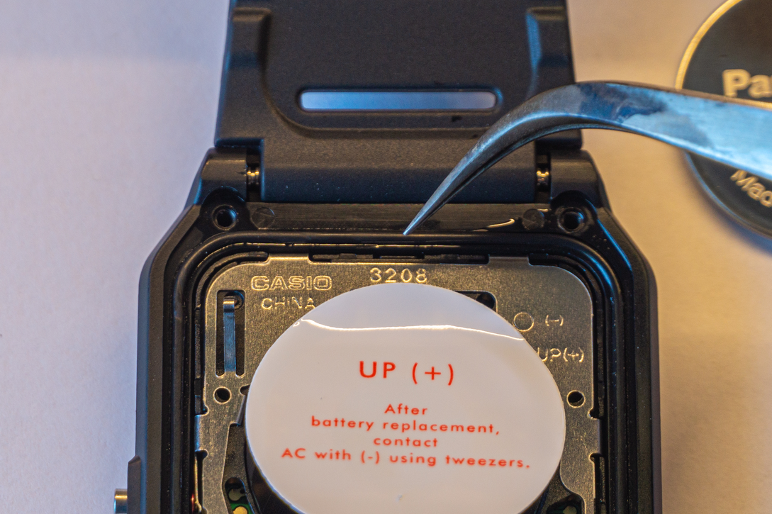
Be careful not to mangle or deform these detents, otherwise the inner case just easily pops out.
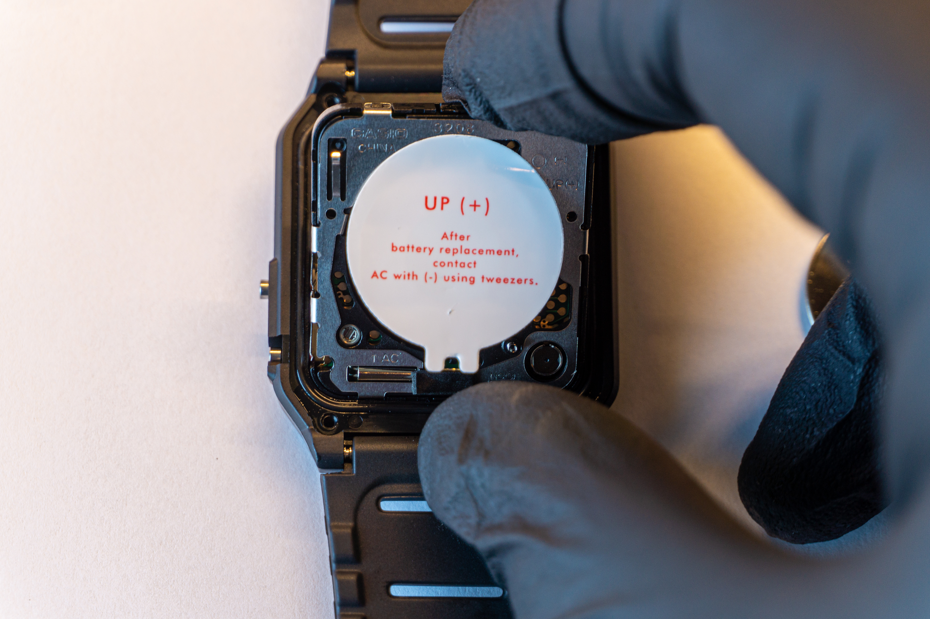
There's a rubber gasket that makes the whole case water resistant. You can keep it in place or remove it, just pay attention not to damage it.
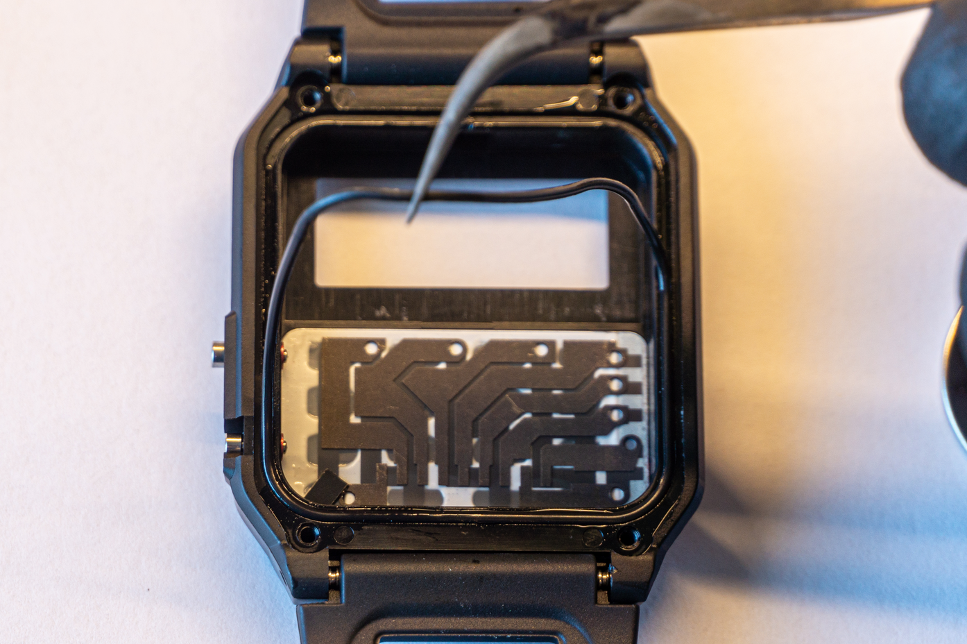
Two halves of the inner case are held together by 7 metal latches. You'll want to be very careful when undoing these, as they are easily bent out of shape which makes later assembly and proper fit more difficult.
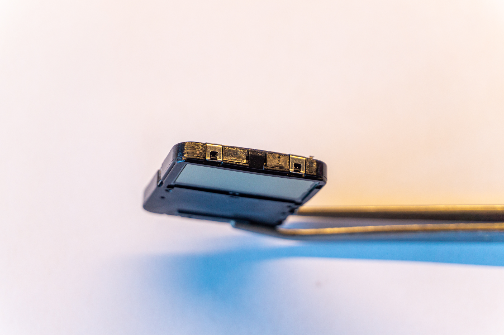
After all 7 are undone, the case can be split open. Again, keep an eye on that spring.
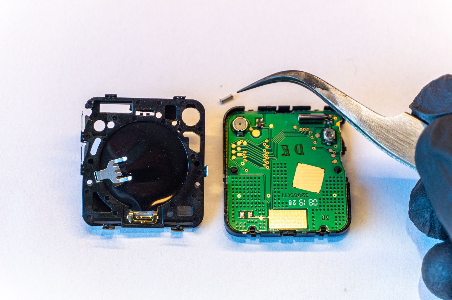
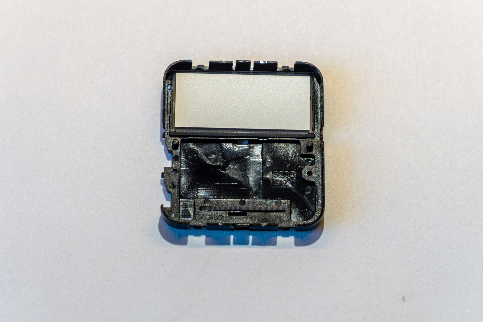
Now you can easily lift the original board out. Make sure that the two ribbon connectors (keyboard and LCD) stayed in the case, as they can sometimes stick to the board. You don't want to lose them.
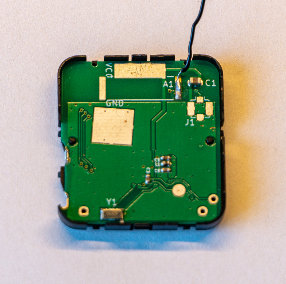
Now the new board can fit in the case snuggly. Notice that I use a wire-wrap wire as an antenna here. If you are using a metal band watch, this wire can be short as you'll be connecting it to the watch band itself. For plastic watches, a quarter-lambda length of wire is optimal (about 16cm for 440Mhz). You will want to solder it to pad A1 as flush with the board as possible.
To get the antenna out of the case, you want to thread it through the hole on the battery part of the inner case first.
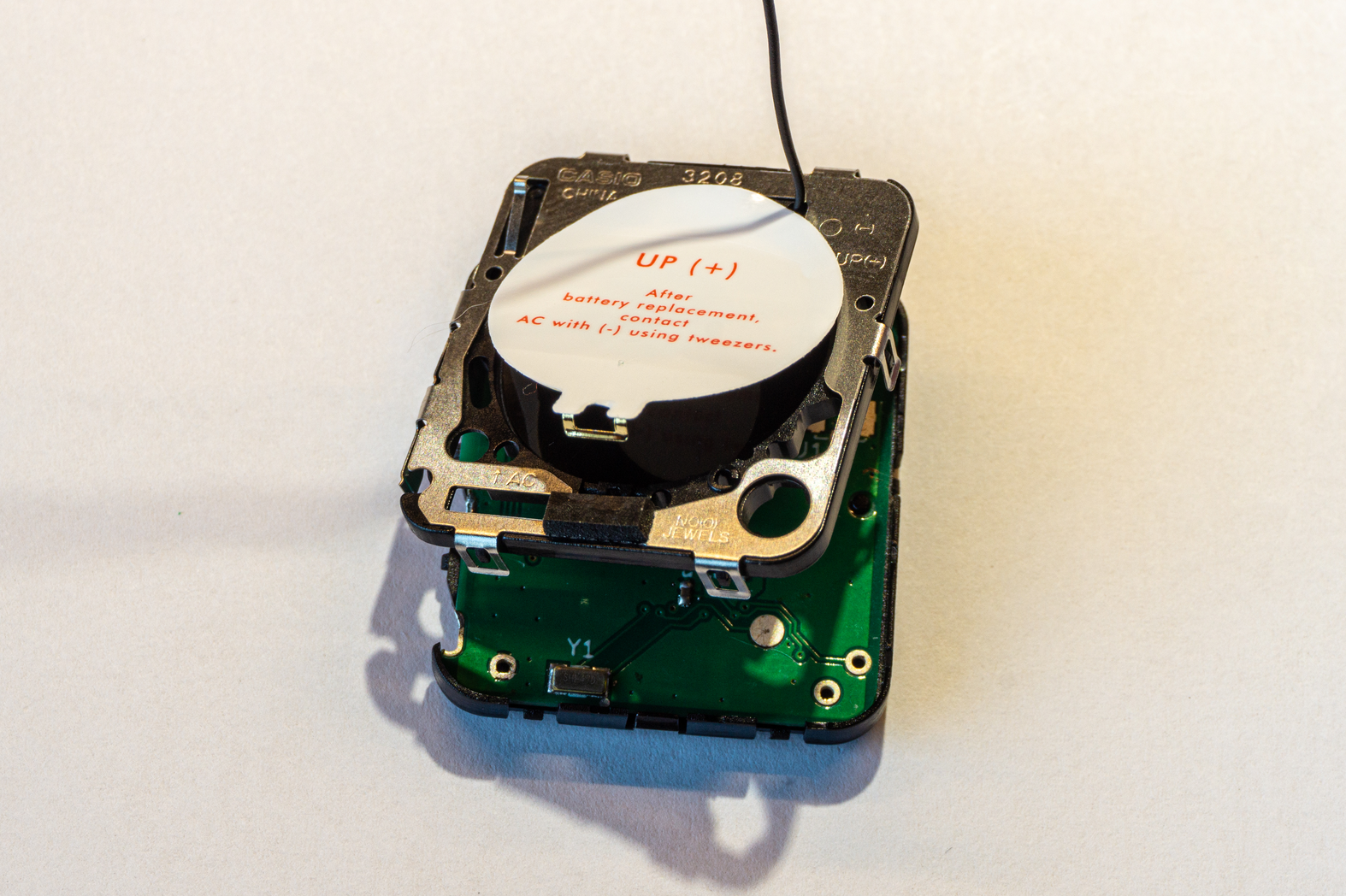
Next step is to carefully redo the metal latches that keep the inner case together. Make sure they are properly latched as this provides proper pressure on ribbon connectors so LCD and keyboard can work properly. It also makes further assembly easier.
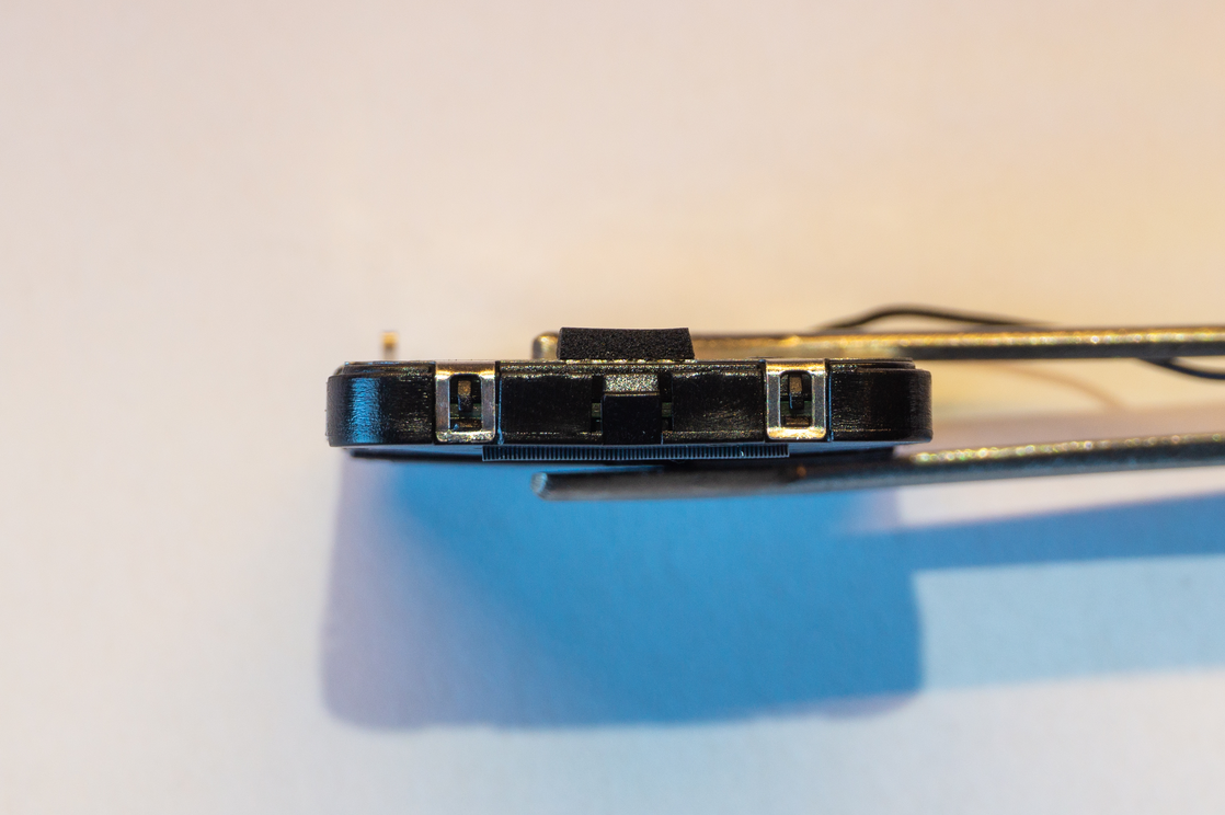
Button latches are particularly stubborn and easily bent. Be careful with those, they have a tendency to spring open.
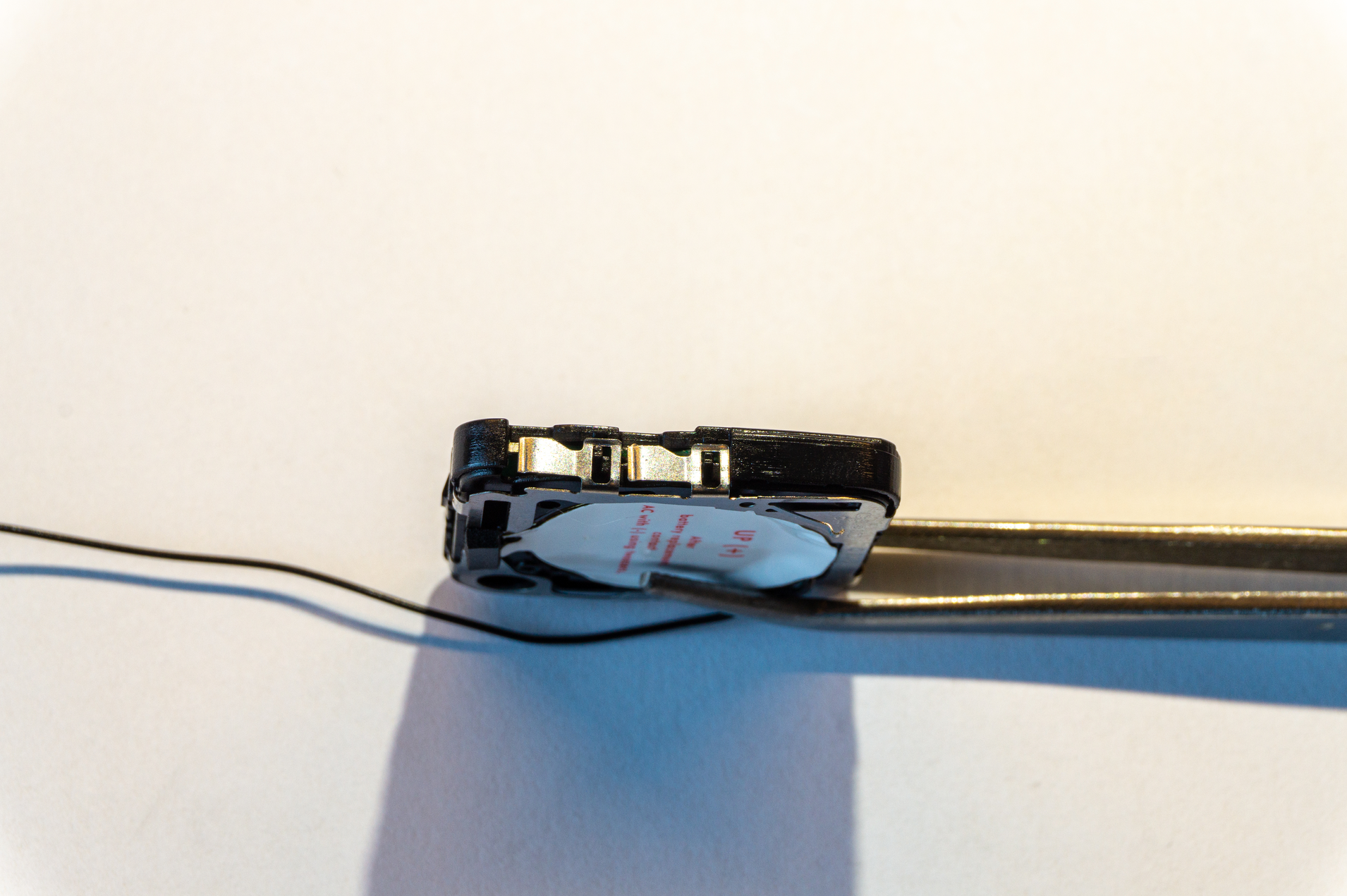
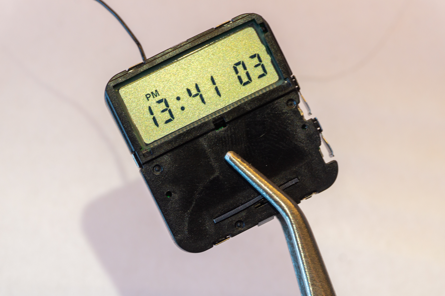
That's the difficult part of the assembly done. Pop the battery back in for a second and verify that you can at least see all the display segments. You can cycle through the apps by pressing the top button. This will light up different parts of the LCD. If the segments aren't lighting up correctly, recheck the metal detents. If those are ok, you might want to make sure that LCD and keyboard pads are clean of solder blobs or flux residue. Also, it doesn't hurt to wipe the ribbon connectors.
Next up is putting the inner case back inside the watch case. Before doing so, make sure both buttons are not pressed in as they can get in the way.
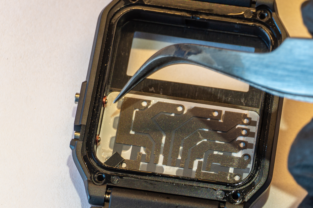
To get the inner case back in, I first push in the buttons side. Otherwise, I noticed that buttons can easily catch on the metal button contacts and undo that side of the inner case.
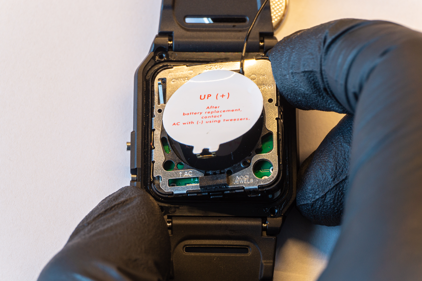
When you put the inner case in, it should sit pretty flush with the rest of the watch case. If it doesn't, it will put additional strain on the screws which can easily strip the threads of the plastic holes.
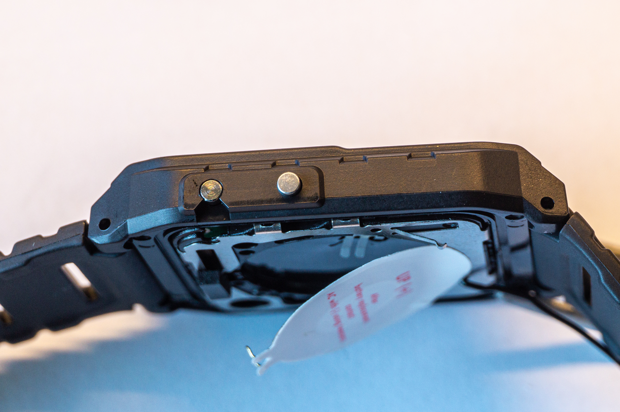
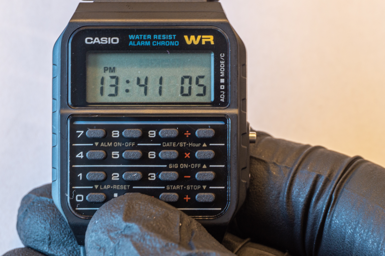
Pop the battery back in again and verify that the display still works correctly.
If you haven't lost that damn spring put it back in place. It might actually be easier to put it back before the two parts of the case are snapped together, but then you have to make sure it doesn't fall out.
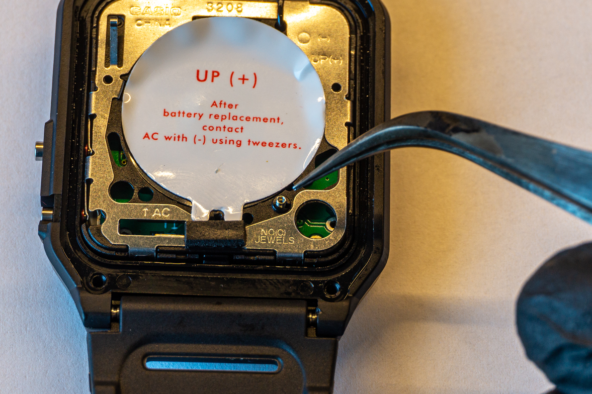
If you've removed the rubber gasket, now is the time to put it back in place. Make sure that the antenna goes over it.
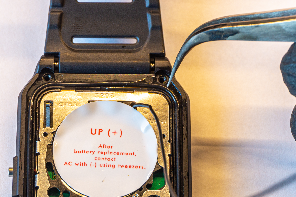
Since we aren't doing any modifications to the case to get the antenna out, there's a bit of pressure on it where the battery cover presses on it. Add a piece of electrical tape there just for good measure.
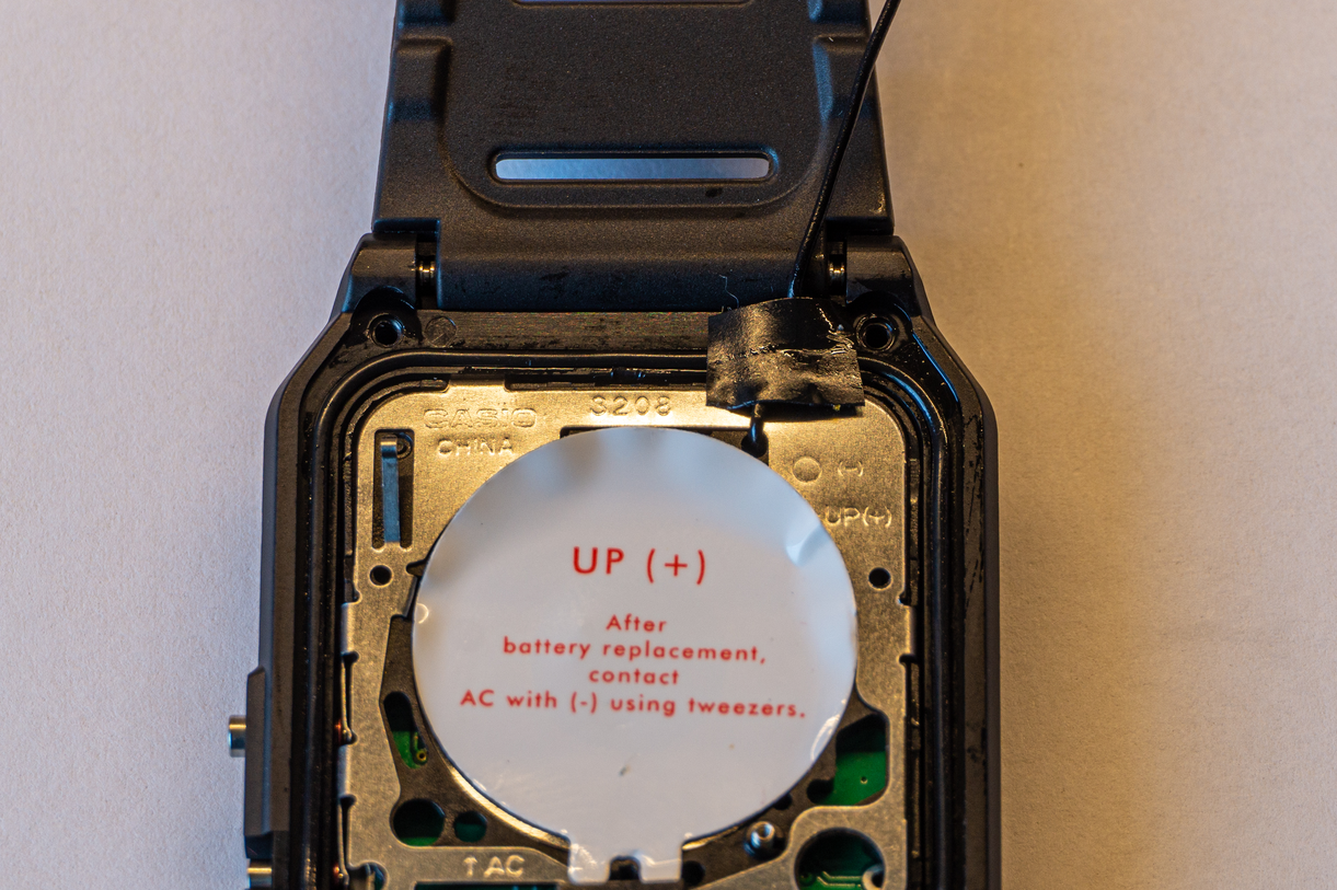
Only one more thing to pay attention to. Proper cover orientation is required to make sure the buzzer is in contact with the buzzer spring.
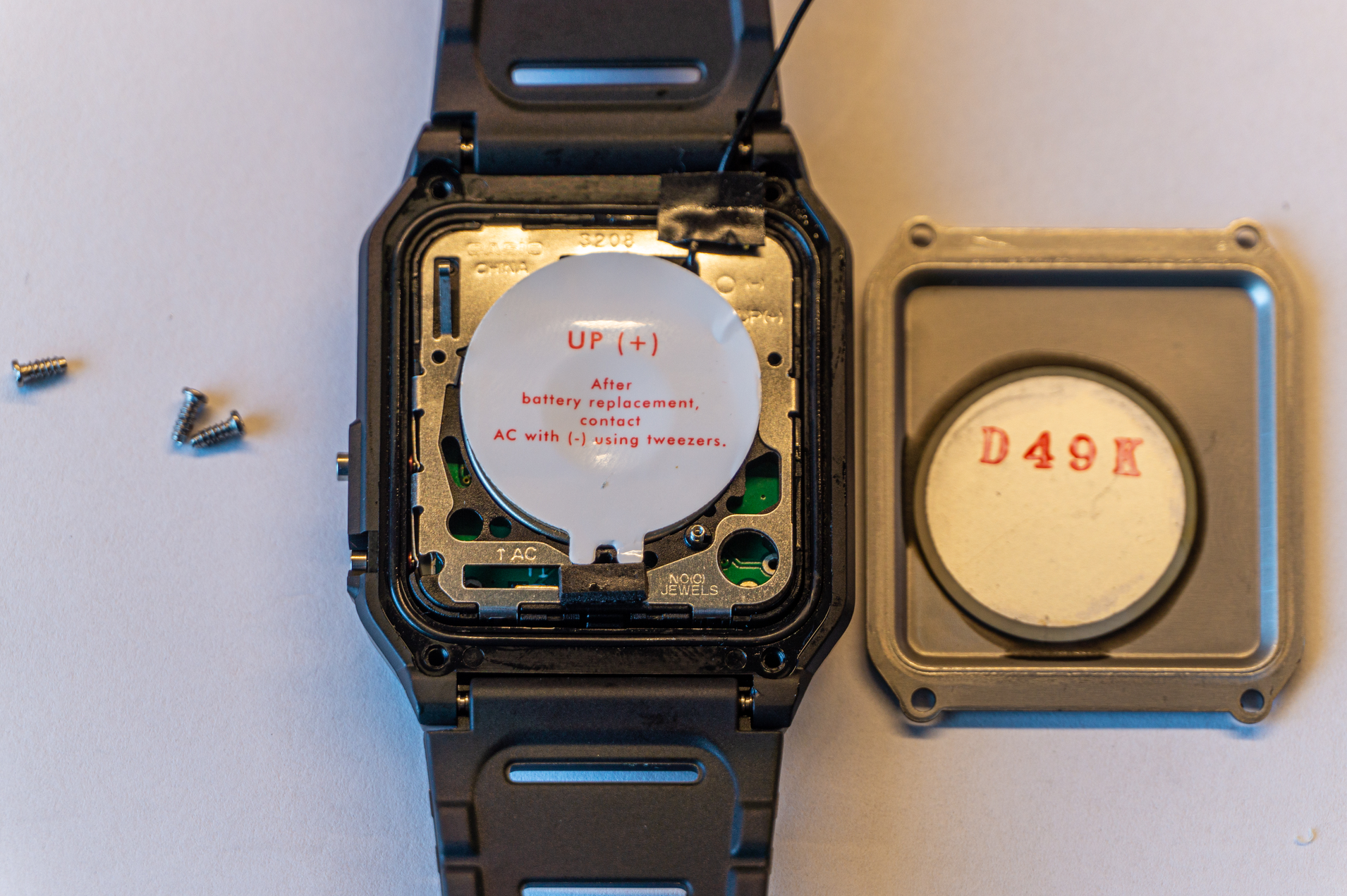
Put a new battery in (one that came with the watch is probably already used up a bit). and screw the battery cover back. Don't over tighten the screws as you can easily strip the plastic threads. And we are done.
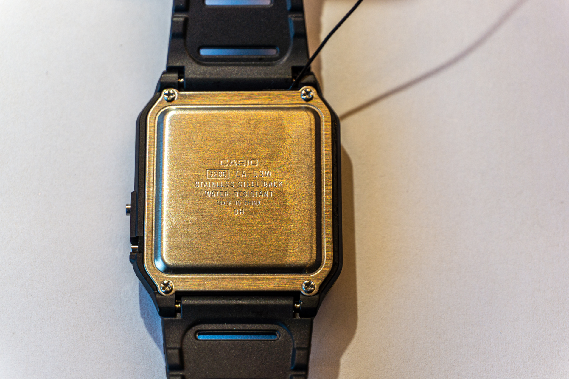
Now check that all the keyboard buttons work and that the watch functions properly and that's it.
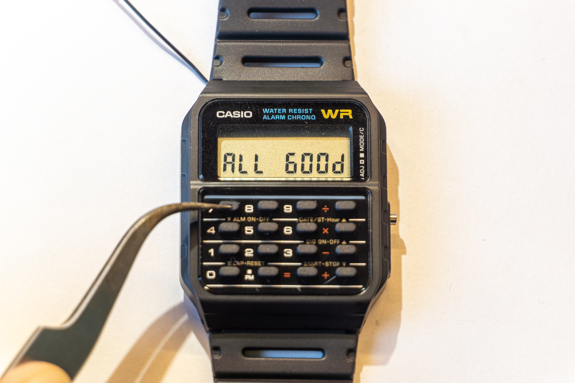
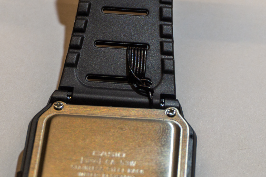
For plastic watches, you can keep the antenna wire loose or loop it inside watch band holes. Looping it is obviously not ideal, but is good enough and, if your wire is black, it's even less noticeable.
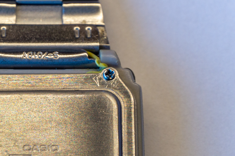
If you are making a watch with a metal band, strip a decent length of the wire and thread it inside the watch band hinge to make electrical connection. The one in the following picture has survived for almost a year now.
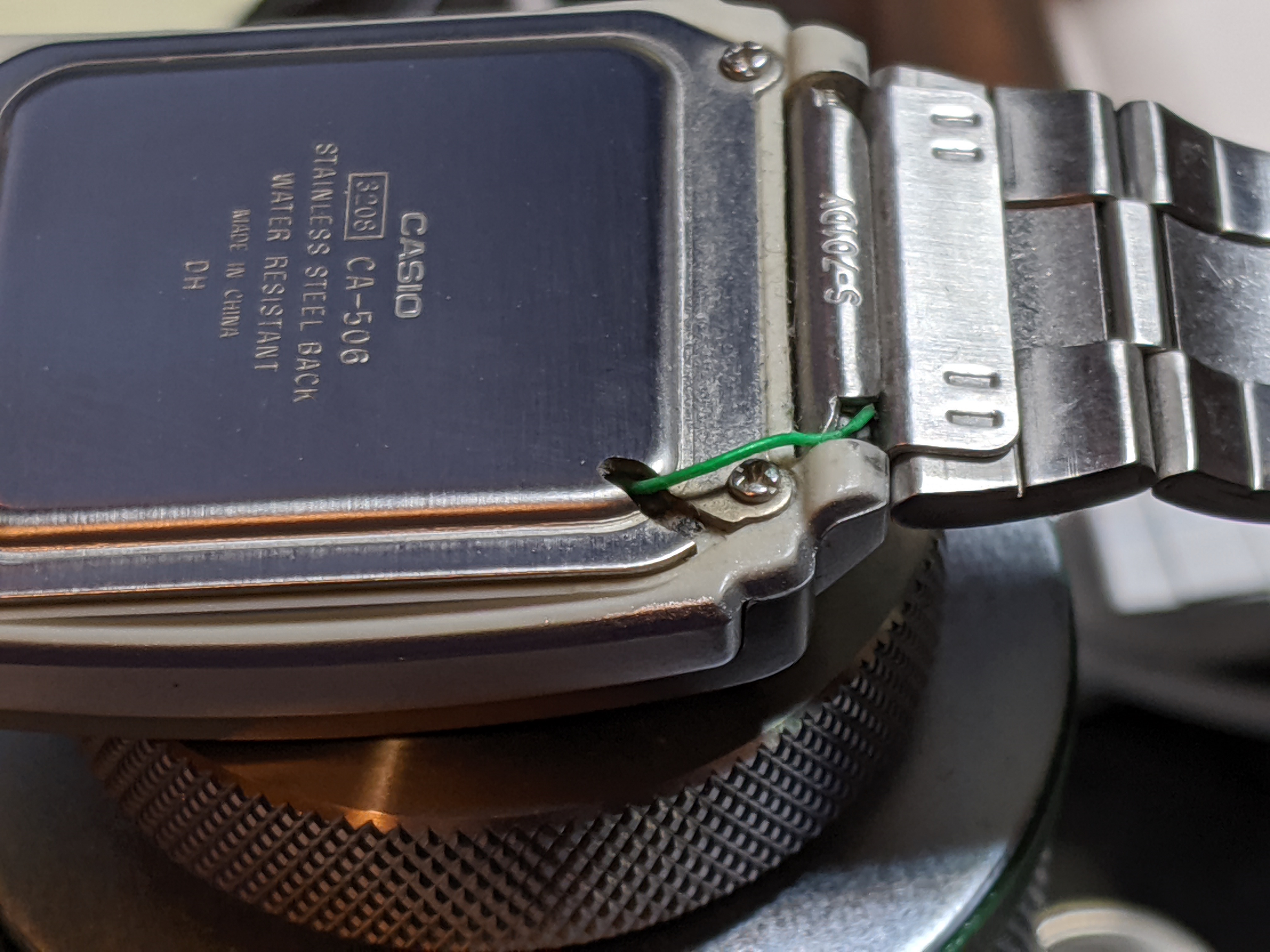
Movement of the hinge and backplate pressure will, over time, strip the insulation which will short the antenna to ground. To keep the strain off the antenna wire completely, you can use a Dremel to cut a small slit into the backplate.
Enjoy!